fMRIPrep 20.2.3 directly measured B0 map SDC correction created worse functional images

Dear fmriprep experts,

Thanks for your help in advance!
I have some single-band fMRI data and a corresponding field map (in Hz) generated directly from a GE scanner, below please see the folder structure.

└── ses-02
├── anat
│ ├── sub-IRIS009_ses-02_T1w.json
│ └── sub-IRIS009_ses-02_T1w.nii.gz
├── fmap
│ ├── sub-IRIS009_ses-02_run-00_fieldmap.json
│ ├── sub-IRIS009_ses-02_run-00_fieldmap.nii.gz
│ └── sub-IRIS009_ses-02_run-00_magnitude.nii.gz
└── func
├── sub-IRIS009_ses-02_task-conscious_acq-sb_dir-pe1_run-00_bold.json
├── sub-IRIS009_ses-02_task-conscious_acq-sb_dir-pe1_run-00_bold.nii.gz
├── sub-IRIS009_ses-02_task-rs_acq-sb_dir-pe1_run-00_bold.json
└── sub-IRIS009_ses-02_task-rs_acq-sb_dir-pe1_run-00_bold.nii.gz

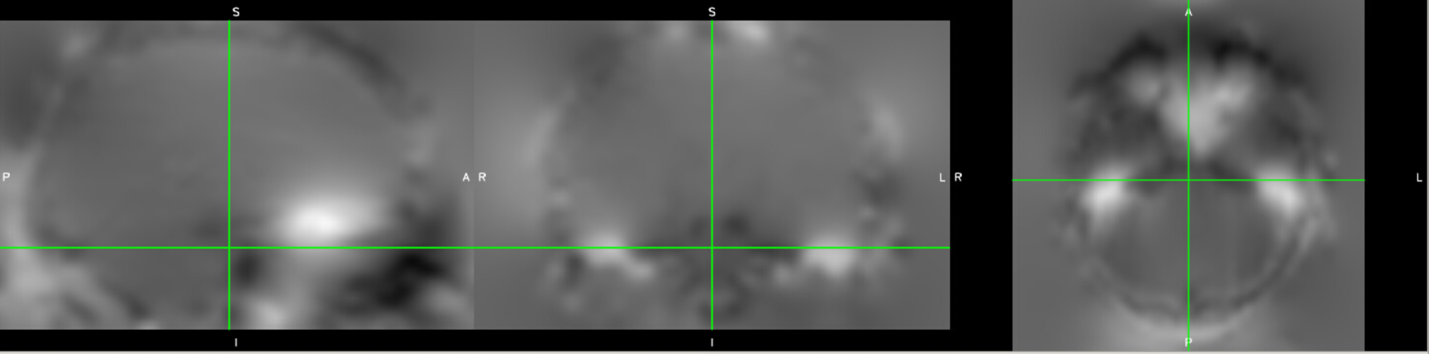
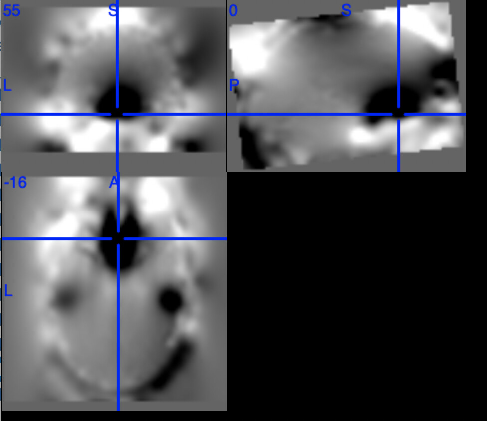
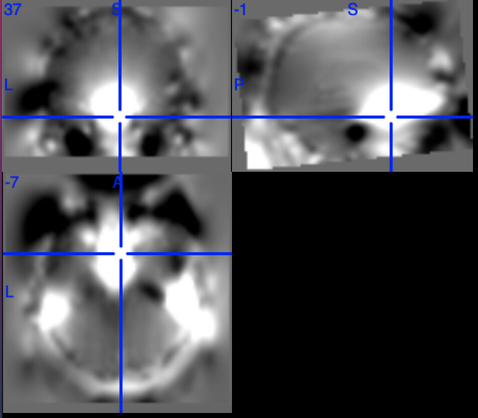
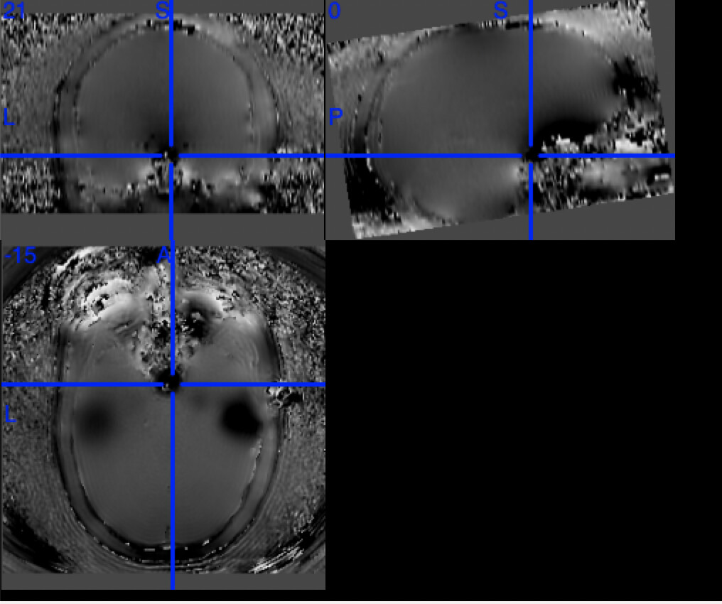
One example of the scanner-generated field map.

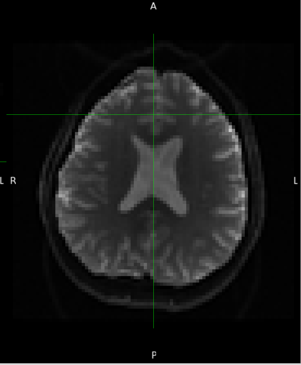
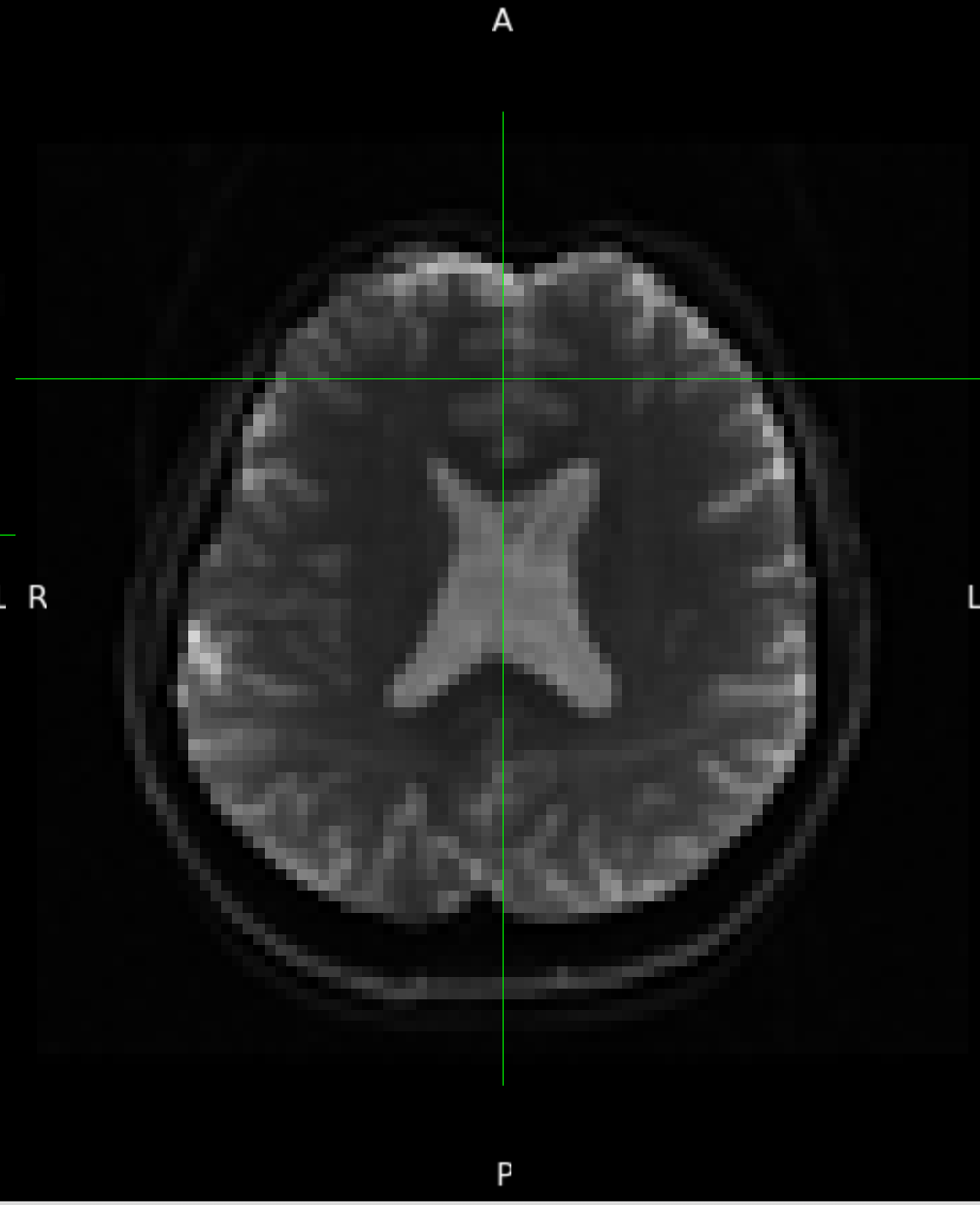
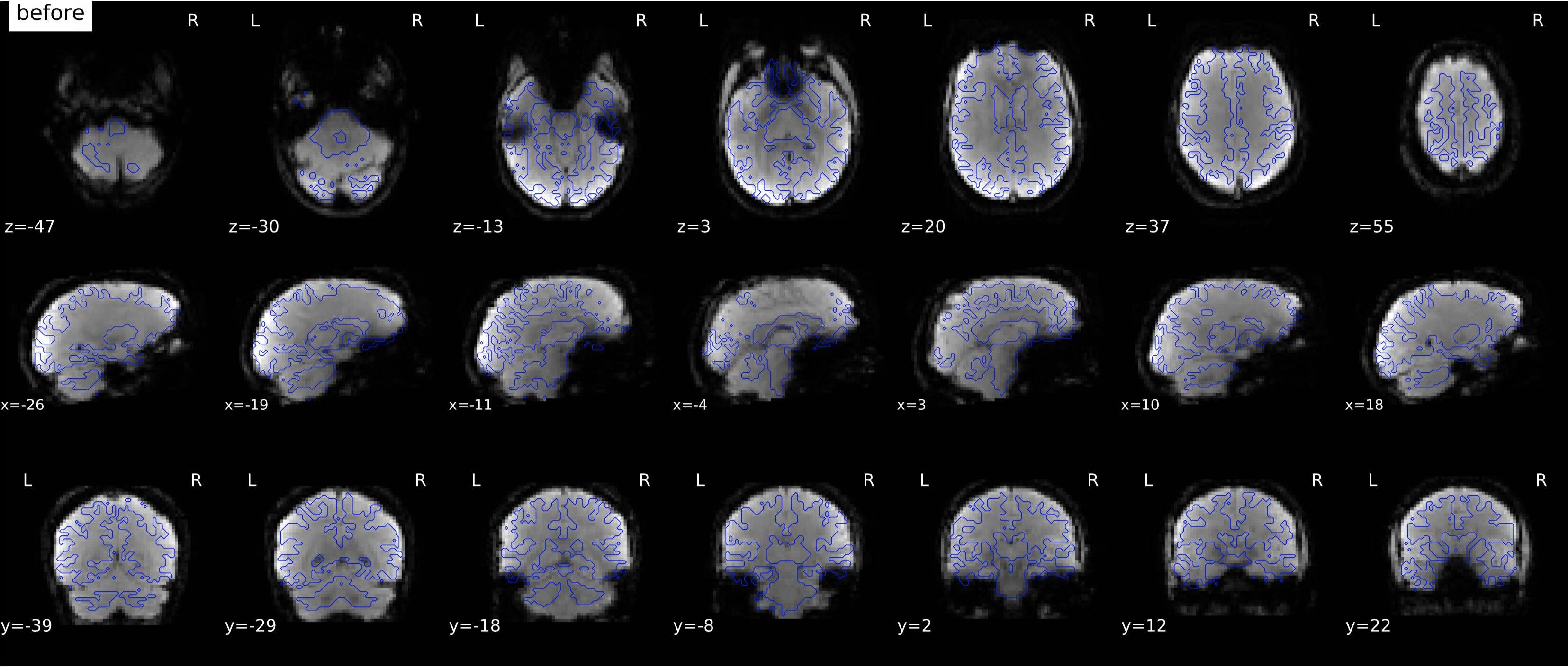
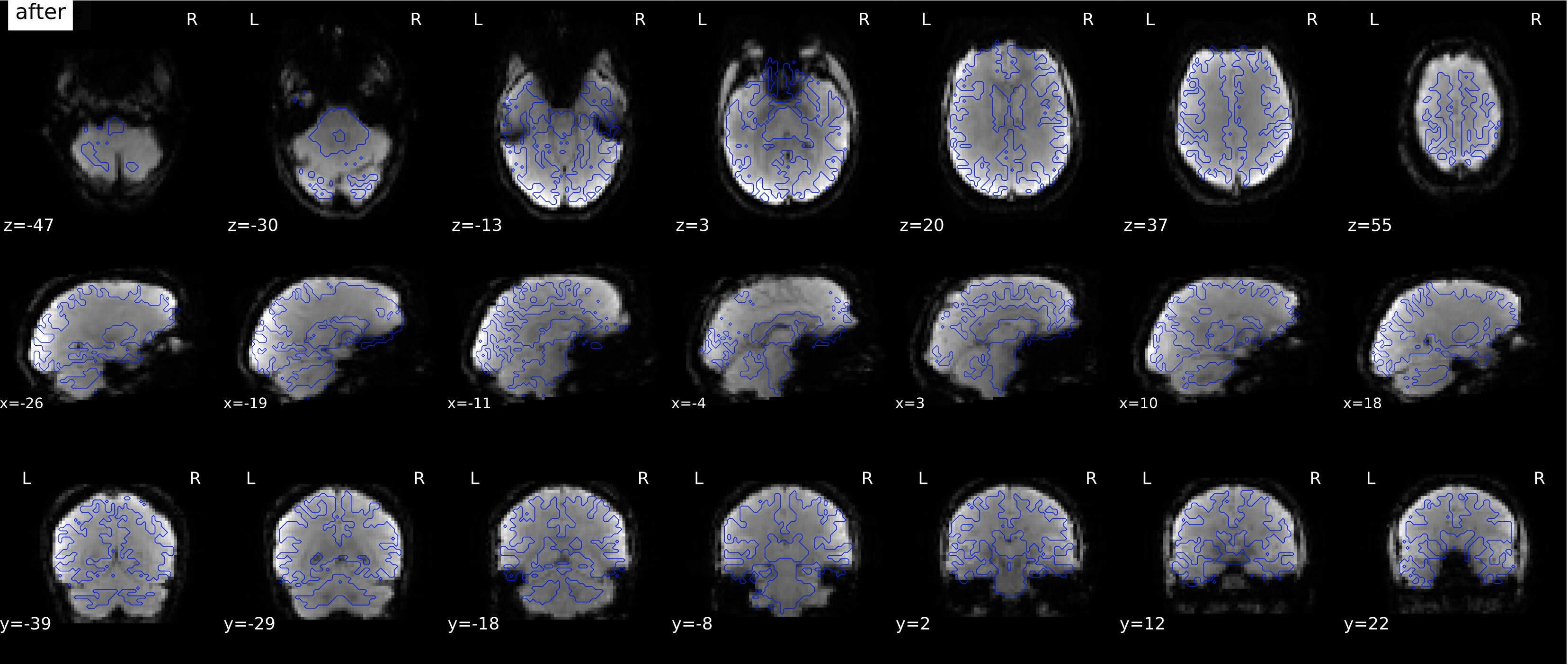
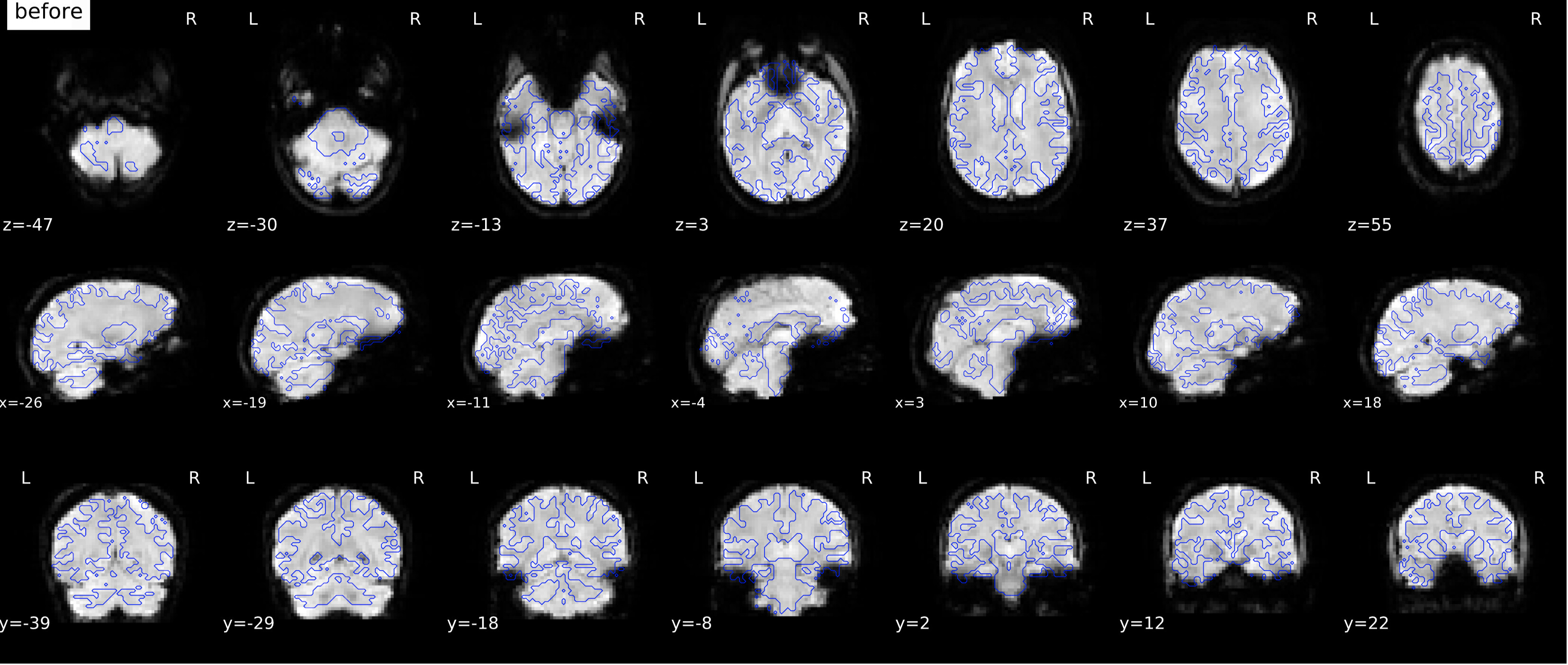
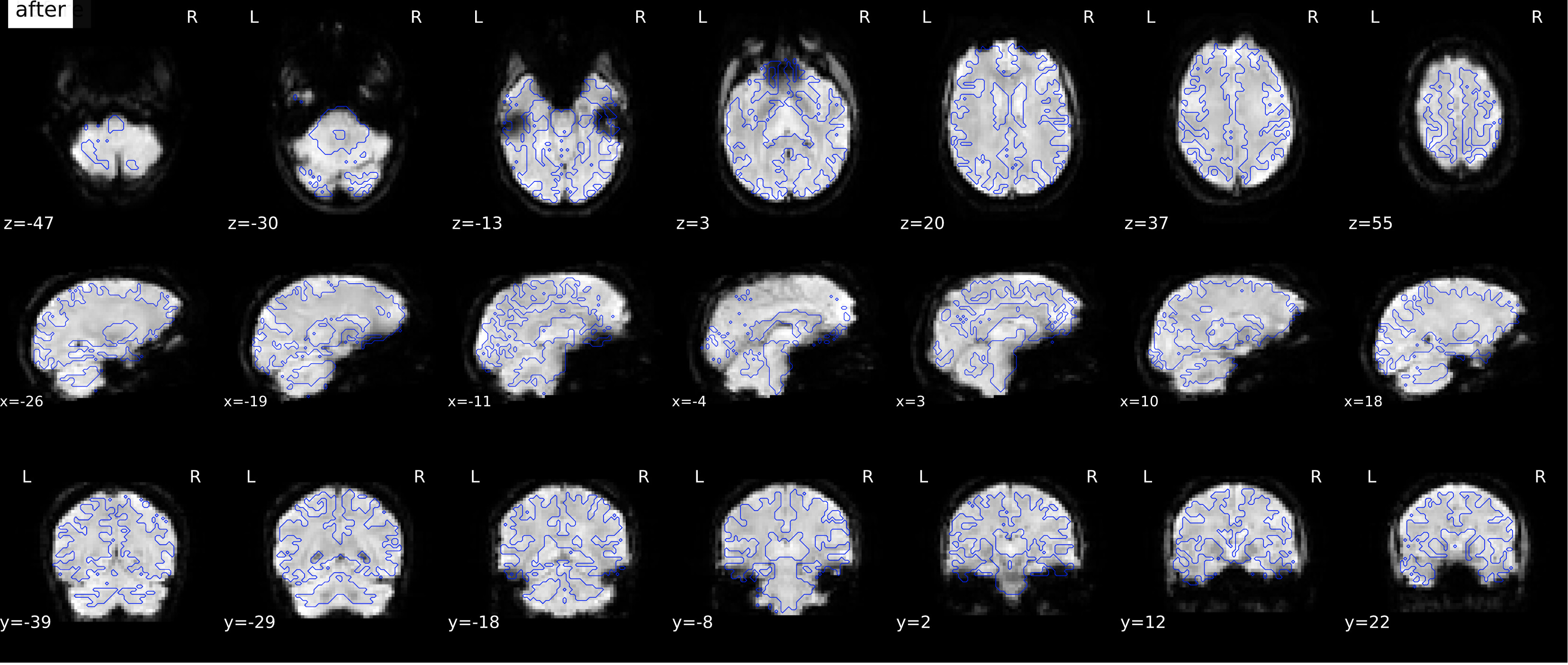
According to the summary report, fMRIprep used FMB (fieldmap-based) - directly measured B0 map in the SDC. Somehow the images after susceptibility distortion correction (SDC) in fMRIPrep 20.2.3 were even worse - more distortion, especially in the medial frontal area and the brainstem (see below). Sorry, it’s less obvious than a gif.


I checked the phase encoding direction of the fMRI data and it was correctly written in the .json sidecar - here it’s AP, our Nifti files (the functional data and the field map) are in LAS orientation, so PhaseEncodingDirection = j-.

If I flip the phase encoding direction to PA, so PhaseEncodingDirection = j, the correction seems correct, however, based on the imaging protocol and the distortion, the phase encoding direction should be AP instead of PA.


I wonder,
(1) if the field map should be somehow multiplied by -1 (flipped its sign) to be entered into fmriprep - I tried to do so and the corrected images looks the same as flipping the PE direction.
(2) if fMRIprep reorients functional images during/before SDC correction, but does not change the PhaseEncodingDirection.

Any suggestion will be appreciated!

1 Like

Hi,

In my opinion, the correct answer may be:

(1) if the field map should be somehow multiplied by -1 (flipped its sign) to be entered into fmriprep - I tried to do so and the corrected images looks the same as flipping the PE direction.

Indeed, here is how a fieldmap (in Hz, grayscale colormap) looks on our dataset:

As you can see, in the temporal cavities and in the frontal sinuses, the intensity in high (white color) , which represent a positive offset of the B0 shift. In your fieldmap, the colors seems reversed.
This fieldmap I show is generated by FSL-topup from on a pair AP-PA phase reserved SE-EPI images used to correct our functional images.

Which scanner do you use to generate the fieldmap you show?

Hi Jsein,

Thanks for your reply and the example of your fieldmap.

I had the same suspicion, and luckily we also collected a pair of AP-PA phase reversed SE-EPI images in the same session for some other multiband fMRI data, so I also generated a fieldmap from this pair to compare with the direct B0, however it looked like my above fieldmap.

More interestingly the fMRIPrep SDC corrected images look correct for these multiband fMRI data using this pair of AP-PA phase reversed SE-EPI images. So I decided to open this thread to ask help. I feel it’s something related to the different process of direct B0 SDC and the PEB/PEPOLAR SDC.

Our data were collected on a GE scanner, the direct B0 fieldmap was generated by a research spiral sequence.

This is interesting!
I guess you entered the correct phase encoding directions in the acquisition_parameters.txt file for topup?
If you look at the topup user page, the fieldmap shown there has also higher intensity in the frontal sinuses and temporal lobes:
https://fsl.fmrib.ox.ac.uk/fsl/fslwiki/topup/TopupUsersGuide

If possible, could you show how look the raw AP and PA SE-EPI images? Depending on the sequence, there maybe a special parameter hidden that flips the phase encoding direction in the sequence, i.e. you think you prescribe a A->P phase encoding but it is actually P->A.

Thank you for your reply again! You are right, the values I put into the acquisition_parameters.txt were incorrect because the example AP-PA phase reversed SE-EPI images I used were in LPS instead of LAS orientation. After changing the orientation to LAS - just to match the direct B0 and to avoid any confounding effect, I did the following:

[1] fslmerge PA and AP SE-EPI images.
PA


AP

[2] generate acquisition_parameters.txt. Because here the image orientation is LAS, so PA should be 0 1 0 in the first three columns while AP should be 0 -1 0.

0 1 0 0.04914
0 -1 0 0.04914

[3] generate fieldmap in Hz

topup --imain=merged.nii.gz --datain=acquisition_parameters.txt --config=b02b0.cnf --fout=my_fieldmap --iout=se_epi_unwarped

The generated fieldmap does look similar to your fieldmap and the one on the topup website in terms of the orbital frontal and temporal lobe.

Now I think I understand that I will need to reverse my direct B0 fieldmap to make FSL fugue (and hence fMRIPrep) work. It’s very interesting though why the fieldmap is collected in a reversed way.

Thanks so much for your help!

Thank you for your feedback and I am glad you understood what was going on.

It may be something speak about with your GE application specialist to understand this behavior with the calculated fieldmap by the scanner.

For anyone who uses GE scanner and has such direct B0 fieldmap, and meets this same problem.

I did more tests yesterday and it seems it’s a matter of orientation and its relation to phase encoding direction. I have some functional data with A>P phase encoding, and some functional data with L>R, all converted in the LAS orientation (default orientation from dcm2niix for my data). If I just flip the sign of the spiral fieldmap (in LPS orientation), very interestingly, images after correction only look good for images with A>P phase encoding, while images after correction look worse for images with L>R phase encoding.

So what happened? According to FSL TOPUP, the phase encoding direction (j- or j or y- or y) is relative to the image orientation (LPS or LAS in our case), and given the B0 offset is calculated in the LPS coordinates – unfortunately, neuroimaging packages do not check this, so, if our fmri data is converted in an opposite direction in one axis comparing to the spiral fieldmap and the axis happens to be the phase encoding axis, we need to flip the sign of the fieldmap (the A>P phase encoding images in this case). Otherwise, we don’t need to if the opposite axis does not happen to be in the phase encoding direction (the L>R phase encoding images).

Now to solve the problem for all functional images using this spiral map, I just re-orient them into LPS and the results now look correct to me.

2 Likes

Hi, I’m having the same problem with my data but am confused as to how I should be re-orienting the phase encoding direction. My fieldmap json file indicates the phase encoding direction is “j”. Where can I tell whether the image orientation is LAS or LPS, and how to change that?

Hi you could use fslhd to tell the orientation of your data.
For example, my following data has an LPS orientation.

fslhd MRI. nii

qform_xorient Right-to-Left
qform_yorient Anterior-to-Posterior
qform_zorient Inferior-to-Superior

Assuming you have a direct b0 map collected just as my case, then what you want to do is to make sure function data is in the same orientation as the b0 fieldmap. And you may also want to change the phase encoding direction if a flipping is made in the phase encoding direction.

Re how to change the orientation, I use fslreorient2std or nipype:
from nipype.interfaces.image import Reorient

I hope it helps.