Using some of the intermediate outputs of QSIRecon (like the normalized wmFODs and atlas parcellations), I would like to, for a single region of the AAL parcellation, make a connectivity footprint from each voxel in that region to the other AAL regions. I figured that using the full QSIRecon may not allow me to find the streamline origins voxels, and it is also important that each voxel is sampled the same amount of times, so I am going to redo tractography from the region of interest.
The MRtrix command I was thinking of using tckgen -act ACT.nii.gz -backtrack -crop_at_gmwmi -seed_random_per_voxel fusiform_R.nii.gz 5000 -include everything_besides_fusiform_R.nii.gz -output_seeds seeds.txt,
where fusiform_R.nii.gz is the seed region of interest, and everything_besides_fusiform_R.nii.gz is a mask that includes everything but the seed region of interest, to make it more likely I am only looking at streamlines that do not terminate in the seed region of interest.
After running, I noticed that there were orders of magnitude more streamlines being created than expected (that is, 5000X#voxels in the mask). Also, the output_seeds text file does not indicate which voxel was seeded (but does provide X,Y,Z coordinates).
Essentially, I am trying to do this but with MRtrix CSD tractography and one of the QSIRecon atlases (from Osher et al., 2015):
Automated cortical parcellation was performed in each participant’s T1 scan, using the Destrieux atlas (Destrieux et al. 2010) from Freesurfer 5.1 (Fischl et al. 2002, 2004) to define 148 cortical regions. … We used the DWI-registered parcels as seed and target regions for fiber tracking…The principal diffusion directions were calculated per voxel, and probabilistic diffusion tractography was carried out using FSL-FDT (Behrens et al. 2007) with 5000 streamline samples in each seed voxel to create a connectivity distribution to each of the target regions, while avoiding a mask consisting of the ventricles. Each of the 148 regions was used as a seed region and tractography was carried out to all 147 remaining regions, or targets. Thus, every voxel within each parcel is described by a vector of connection probabilities to each other brain region.
As soon as I get the voxel-wise tracts, making a fingerprints with the QSIRecon atlas files should be trivial. But am I misguided trying to do something analogous to this in MRtrix? I am not quite sure how MRtrix does seeding compared to probtrackx.
There are some differences in FDT and mrtrix that could make this tricky. That paper says the weights in their fingerprints are “connection probabilities”, which sounds suspicious, but you could calculate streamline counts or average SIFT weights using the data you already have.
For creating the fingerprint matrix you might be able to do something like this:
For each streamline in the tck file
Assign it an ID and figure out which region pair it connects
Figure out which voxels (i, j, k) the streamline passes through
In a lookup table, make sure that each (i, j, k) key knows that a streamline with ID passes through it.
The lookup table would look something like (in python)
Where keys are i,j,k voxel coordinates and values are lists of streamline IDs.
Then for each voxel (i, j, k) in the cortical ribbon
Look up which streamline IDs pass through it
Aggregate which region pairs it connects and calculate the fingerprint vector
You should have the SIFT weights and the tck file in the QSIRecon outputs. I wouldn’t worry about where the streamlines were seeded - what matters is where they end up in gray matter. The streamline reader in Nibabel can do most of the coordinates-to-voxel mapping you’ll need.
Ultimately, I will have to assign streamline beginning locations to functional voxels (that is why I asked the earlier question here about aligning fMRIPrep and QSIPrep derivatives, which I am still working on).
EDIT: I now realize that the streamlines can extend bidirectionally from the seed, which is why the seed point doesn’t matter in this context.
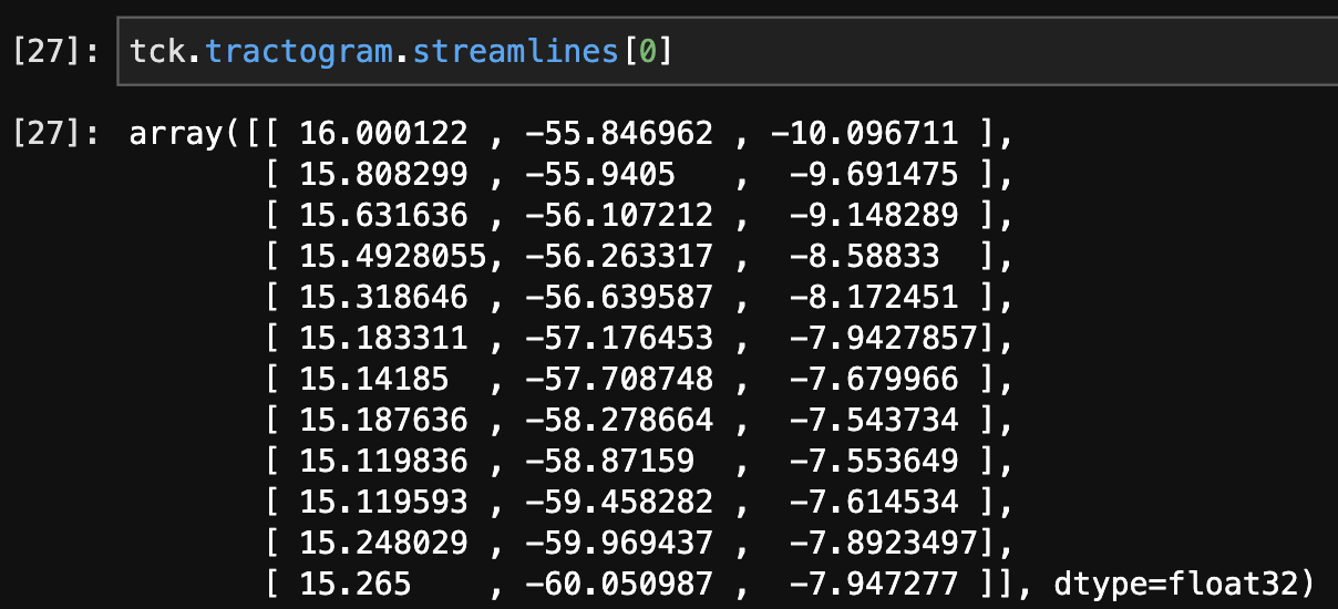
I have loaded a tractogram in Nibabel and got the following output when exploring its data structure:
Would it be right to say that the first and last tuples are the beginning and ending coordinates of the streamline? If so, this could just be a matter of finding streamlines whose beginning/end intersects with the binary mask I made of the parcellation region, and then assigning those to different voxels using the functional images sampling scheme.
I wouldn’t get too hung up on “beginning” and “ending” of the streamlines. A lot of papers conflate streamline endpoints with the beginning and ending of axons. In reality, streamline termination is usually due to the fiber propagation algorithm stopping at a voxel with low signal or peak directions incompatible with the nearest trajectory of the streamline. The diffusion signal tends to be messy at the cortical GM/WM interface and there can also be very sharp turns made by axons as they go through that tissue - both result in streamlines terminating. In subcortical gray matter you see large projections where it’s really unclear where the actual axons are beginning and synapsing.
My preference in calculating connectivity is to use the “pass” approach (in DSI Studio terminology) where if a streamline passes through a voxel it counts toward that voxel’s connectivity to the rest of the brain. We’ll never know for sure with current DWI methods if a cell bodies in a specific voxel have axons projecting outward or whether those axons enter and leave the voxel somewhere earlier. You will also end up with unnecessarily sparse estimates of connectivity if you strictly require streamlines to terminate in voxels (aka the “end” approach in DSI Studio). When our group was benchmarking different methods of calculating connectivity the “end” method wasn’t very reliable across scans in addition to arbitrarily missing some connections.
Just want to make sure I am approaching this right. Let’s call this streamline index 0. I have 1.2mm isotropic voxels in my ACPC T1-aligned DWI image. To get all the coordinates associated with this tract, would it just be a matter of finding the unique tuples that exist after rounding each of the coordinates to the nearest integer? I suppose it is unclear if these numbers are in voxels or mm, and what space I would ultimately want the table to be in. I can resample the fMRI image to the DWI image after aligning it so that hopefully I could use either as long as I’m consistent.
tck files are in RAS+ world coordinates. The nifti images have an affine that maps from voxel i, j, k to RAS+ world coordinates. You should be able to invert the affine and matrix multiply the coordinates to get them into voxel coordinates.
It turns out this function creates the exact lookup table you proposed! Now figuring out how to filter out non-GM voxels and assign GM voxels to parcels, but that hopefully should not be too difficult.
I have a clarifying question for quantifying edge weights in the “pass” method. In a given voxel in the seed fusiform region, there may be a single streamline passing through that has several nodes in a single target region (defined as a larger parcel in a qsirecon atlas). SIFT weights aside for the moment, should the weight of that streamlines contribution be scaled by how many voxels it passes through in the target region, or is it supposed to be a more binary indication of “does the streamline pass through or not”?
Just to put some numbers to it, lets say a streamline passes through a fusiform seed voxel and 10 voxels in the lingual gyrus. Ignoring SIFT scaling, would the streamline’s contribution to the seed voxel’s fingerprint with the lingual gyrus be 10 (denoting how may voxels the streamline passed through) or 1 (denoting that the streamline passed through it)?
This is definitely in the realm of “no one has benchmarked methodological variations”, so I would recommend going with the simplest possible approach.
Counting passed-through voxels would be hard to justify biologically given how streamline termination is somewhat arbitrary and that the weights could be wildly different if you’re applying the methods to images with different voxel sizes.